SERVICES of characterization and diagnosis
Characterization of optical components (focal length, angles of prisms, surface flatness, dimensional measurements )
Spectral analysis of materials (filters transmission, thin films characterization)
LIST OF INSTRUMENTS
| Crt. No. | Item | Manufacturer | Model | Status |
| 1 | Video measurement microscope | Hoffmann | MM1-300/6X GARANT | New |
| 2 | Laser Beam profiler | Ophir Photonics | NanoScan2 | New |
| 3 | Electronic autocolimator | Moeller-Wedel Optical | Elcomat vario D 500T/65 | New |
| 4 | Interferometer and accessories | Moeller-Wedel Optical | Interferometer VI-direct 100 SL | New |
| 5 | Diopter telescope | Moeller-Wedel Optical | Diopter telescope ±5.0 dpt, 0.1 dpt div. | New |
| 6 | Dynameter | Moeller-Wedel Optical | Dynameter | New |
| 7 | Laser He-Ne CW 633nm | ThorLabs | Laser and accessories | New |
| 8 | Laser diodes CW 405, 532, 635, 859 and 1064 nm | ThorLabs | Laser and accessories | New |
| 9 | Laser UV 355nm CW | Roithner | Laser and accessories | New |
| 10 | Optical Spectrum Analyzer | ThorLabs | OSA 201, OSA 202 | New |
| 11 | Polarization analyzing system | ThorLabs | PAX57VIS-T, PAN5710IR2 | New |
| 12 | Ultrafast photodiode | Alphalas | UPD-200-UP | New |
| 13 | Oscilloscope | Tektronix | DPO7254 | Exist. |
| 14 | Spectrophotometer | PerkinElmer | LAMBDA 1050 UV/Vis/NIR | Exist. |
| 15 | Ellipsometer | HORIBA | UVISEL ER AGAS | Exist. |
| 16 | Energy/Powermeter | Gentec | SOLO PE | Exist. |
| 17 | Goniometer | Moeller-Wedel Optical | Goniometer II-VIS | Exist. |
| 18 | Focal length meas. device | Moeller-Wedel Optical | MELOS 530-3 | Exist. |
LASER ENERGY/POWER
One of the most important characteristic of a laser source is its energy (for a pulsed laser) or its power (for a CW laser). Measurements can be done at high acquisition rates allowing thus an accurate determination of pulse-to-pulse energy fluctuation. All measured data are stored and processed to get statistics (average, standard deviation, RMS, maximum, minimum, peak-to-peak). Report contains also measurement uncertainty data.
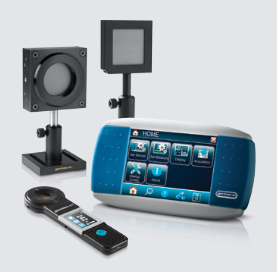
Laser energy can be measured using a Gentec SOLO-PE Energy/Powermeter together with the next measuring heads (QE 50 SP-MB and XLE4):
| Measuring head | QE 50 SP-MB | XLE4 |
| Measured energy range | 15 µJ – 75 J | 100 nJ – 4 mJ |
| Wavelength range | 190 nm – 20 µm | 190 nm – 2.5 µm |
| Sensor area | 50 x 50 mm | Ø 4 mm |
| Rise time | 10 µs | |
| Max. pulse width | 225 µs | 5 µs |
Laser power can be measured using a Gentec SOLO-PE Energy/Powermeter together with the next measuring heads (PH100-Si, PH20-Ge, UP12E, UP25N and UP55N):
| Measuring head | PH100-Si | PH20-Ge | UP12E | UP25N | UP55N |
| Measured power range | 600 pW – 30 mW | 2 nW – 30 mW | 1 mW – 70 W | 3 mW – 300 W | 5 mW – 400 W |
| Wavelength range | 300 nm – 1100 nm | 800 nm – 1650 nm | 190 nm – 11 µm | 190 nm – 11 µm | 190 nm – 11 µm |
| Sensor area | Ø 11.28 mm | Ø 5 mm | Ø 12 mm | Ø 25 mm | Ø 55 mm |
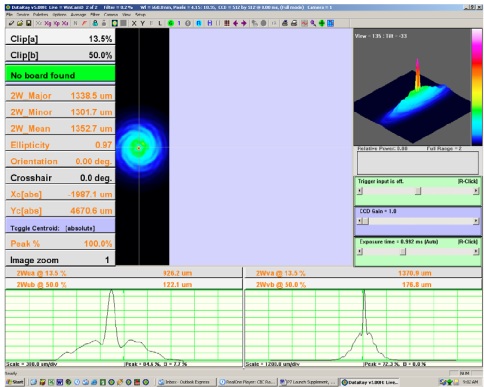
LASER BEAM PROFILE
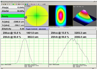
A more precise diagnostic of a laser source requires an analysis of the laser beam profile. A laser beam profiler provides important information characterizing the laser, as the energy (pulsed lasers) or power (CW lasers) distribution in a cross section of the laser beam, the waist of the beam, its divergence and M2 factor (that quantifies the beam quality of laser beams).
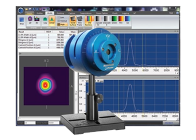
These measurements can be done using one of the next three heads (NS2-Si/9/5-PRO, NS2-Ge/9/5-PRO and NS2-Pyro/9/5-PRO), depending on the required wavelength:
- Ophir NS2-Si/9/5-PRO: NanoScan2 Si Detector 9 mm aperture 5μm slits. High-resolution head featuring Si detector, 63.5 mm diameter head with rotation mount, 9 mm entrance aperture, and matched pair of 5 μm wide slits. Use for wavelengths from 190 nm to 1 μm.
- Ophir NS2-Ge/9/5-PRO: NanoScan2 Ge Detector 9 mm Aperture 5 μm slits. High-resolution head featuring Germanium detector, 63.5mm diameter head with rotation mount, 9 mm entrance aperture, and matched pair of 5 μm wide slits. Use for wavelengths from 700 nm to 1.8 μm.
- Ophir NS2-Pyro/9/5-PRO: NanoScan2 Pyro Detector 9 mm Aperture 5.0 μm slits. High-resolution head featuring pyroelectric detector, 63.5 mm diameter head with rotation mount, 9 mm entrance aperture, and matched pair of 5 μm wide slits. Use for wavelengths from 190 nm to 100 μm.
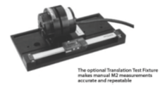
M2 measurements require the use of Ophir RAL-FXT (Rayleigh fixture for manual M2) and Ophir COL-FXT 250 (250 mm FL collimation fixture).
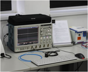
LASER PULSE WIDTH
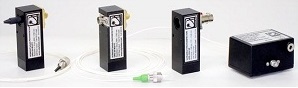
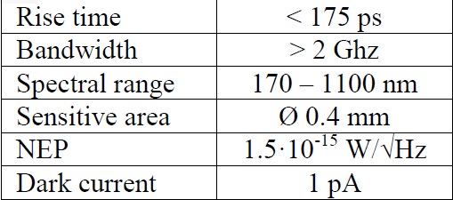
Temporal behavior of the pulsed lasers is characterized by the pulse width (duration). Because the commercially available lasers have pulse widths of few ns, the pulse width measurement requires both a wide band oscilloscope and an ultrafast photodiode. As oscilloscope we use a Tektronix DPO7254, with a 2.5 GHz band and a rise time of 150 ps. The ultrafast photodiode is UPD-200-UP from Alphalas:
All measured data are stored and processed to get statistics (average, standard deviation). Report contains also measurement uncertainty data.
FT OPTICAL SPECTRUM ANALYSIS
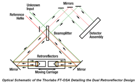
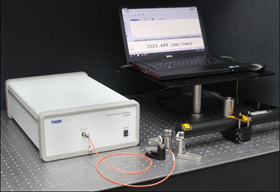
Some lasers need to be verified from the point of view of the emitted optical spectrum. Depending on the spectral domain two Fourier Transform optical spectrum analyzers can be used: ThorLabs OSA 201 (Fourier Transform Optical Spectrum Analyzer, 350 – 1100 nm) or ThorLabs OSA 202 (Fourier Transform Optical Spectrum Analyzer, 600 – 1700 nm). The optical schematic of the FT-OSA is presented below:
Optimized for use in the 350 – 1100 nm spectral range, the OSA201 measures the optical power of both narrowband and broadband sources as a function of wavelength. The maximum spectral resolution of 7.5 GHz (0.25 cm-1) is set by the maximum optical path length difference of ±4 cm, while the high spectral accuracy of ±2 ppm (parts per million) is ensured by simultaneously measuring the interferogram of a stabilized 632.991 nm HeNe laser. For sources with linewidth < 10 GHz, enabling the Wavelength Meter mode provides 0.1 ppm resolution and ±1 ppm accuracy.
Optimized for use in the 600 – 1700 nm spectral range, the OSA202 measures the optical power of both narrowband and broadband sources as a function of wavelength. The maximum spectral resolution of 7.5 GHz (0.25 cm-1) is set by the maximum optical path length difference of ±4 cm, while the high spectral accuracy of ±2 ppm (parts per million) is ensured by simultaneously measuring the interferogram of a stabilized 632.991 nm HeNe laser. For sources with linewidth < 10 GHz, enabling the Wavelength Meter mode provides 0.1 ppm resolution and ±1 ppm accuracy.
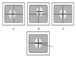
The OSA’s input port is compatible with single mode and step-index multimode FC/PC patch cables with cores up to Ø50 µm. For the highest contrast, single mode patch cables are recommended. To adapt a free-space input to the OSA, the procedures are illustrated next:
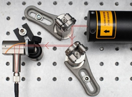
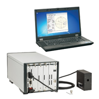
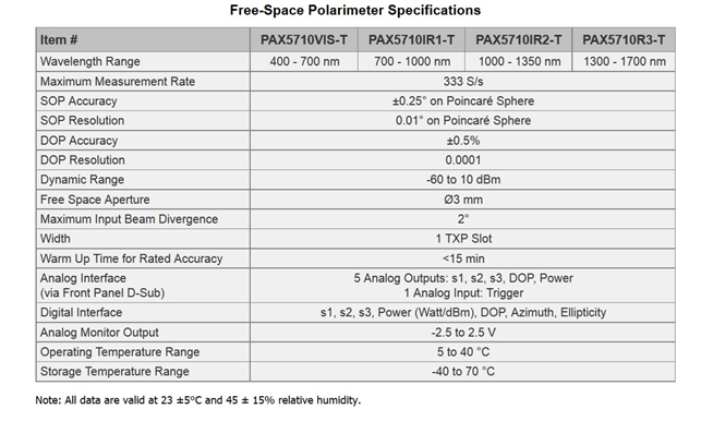
POLARIZATION STATE ANALYSIS
Polarization analysis provides besides classic polarization measurements also evaluation of optical components with the Jones or Mueller matrix algorithm. It can be also used for determining the Extinction Ratio.
We use ThorLabs PAX5710VIS-T polarimeter (TXP Polarimeter including PC, 400 – 700 nm, with external sensor) together with external sensor PAN5710IR2 (1000-1350 nm). It is a free-space polarimeter, with interchangeable external sensor head, the wavelength range is 400 – 700 nm, the dynamic range is 70 dB, the sampling rate is up to 333 samples/s and the accuracy is ±0.2 ° on the Poincare sphere.
CHARACTERIZATION OF OPTICAL COMPONENTS
Characterization of optical components includes measurements as: the focal lengths (effective and back focal length), angle of prisms and flatness of plane surfaces (not only optical).
Dimensions and positions of optical and mechanical components can be accurately measured by a video measuring microscope. Some alignments can be done/verified using an autocollimator or a He-Ne laser.
Measurement of the focal length
Focal lengths (effective and back focal length) can be measured using Moeller-Wedel Optical device MELOS 530-3.
- Range of focal measured focal lengths: 5 mm … 500 mm (positive), -5 mm … -580 mm (negative), 2 mm … 530 mm (back focal lengths)
- Free aperture: 28 mm
- Max. sample diameter: 200 mm
- Reproducibility: 0.04 % (focal lengths) or 0.03 % … 0,2 % (back focal lengths)
- Measurement accuracy: 0.3%


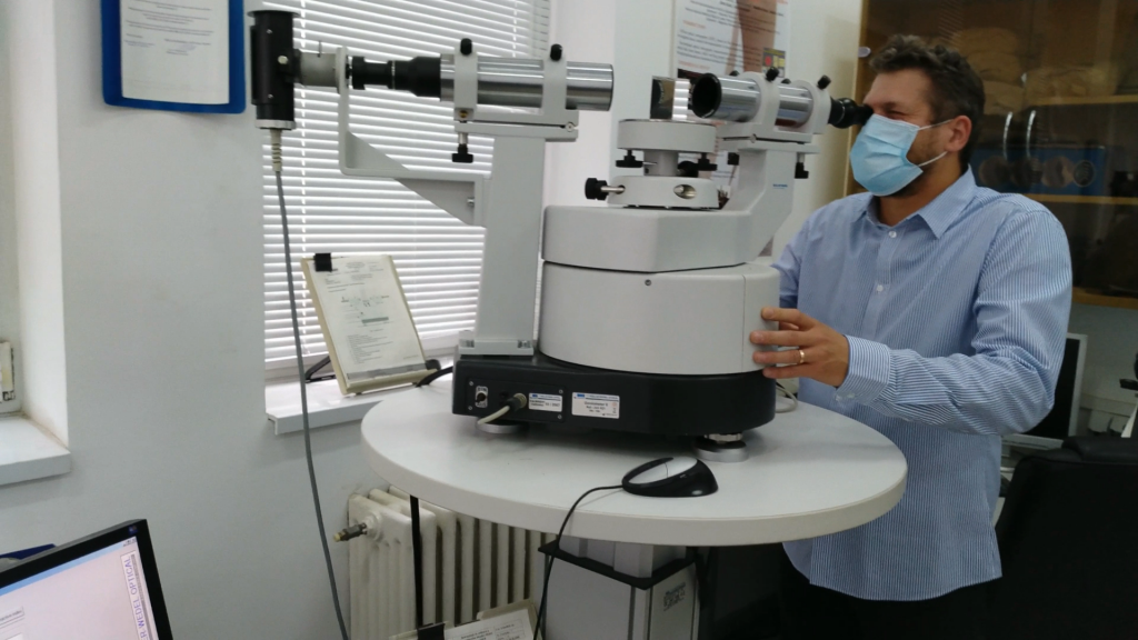
Measurement of the angles of prisms
The angles of prisms and refractive index of the glass are measured using Goniometer Moeller-Wedel model Goniometer II-VIS:
- Telescope/collimator: f = 300 mm
- Accuracy of angle measurement: (mean error of series measurements) < 0.6 arcsec.
- Spectral range: 436 – 650 nm
- Accuracy of refractive index measurements (mean error of series measurements): 10-5
- Alignment: visual with autocollimator
- Reading of incremental circle automatically via computer and built-in counter board
- Evaluation automatically with GONIOWIN software
- Spectral lines : F’ (479.99 nm), e (546.07 nm), C’ (643,85 nm)
Measurement of surface flatness
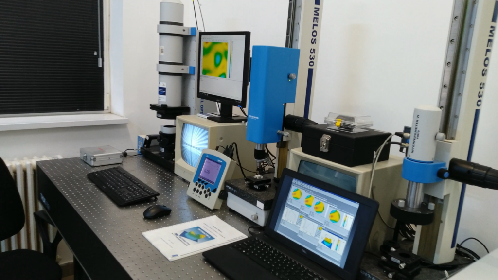
Flatness is determined using the interferometer Moeller-Wedel, model VI-direct SL 100 and the software INTOMATIK-S for fringe evaluation:
- Type of interferometer: Fizeau
- CCD Camera : 752 x 582 pixels
- Laser: fiber coupled He-Ne 632.8 nm
- Exit aperture: 100 mm
- Measurement accuracy: λ/20 (p-v) with software evaluation
- Adjustment range: 530 mm
- Fine adjustment range: 1 µm
- Measurement range: 530 mm
- Resolution: 1 µm
- Accuracy: 3 µm
- Vertical stand with XY- and tiltable table
- 4-axes adjustable mount
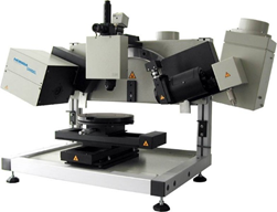
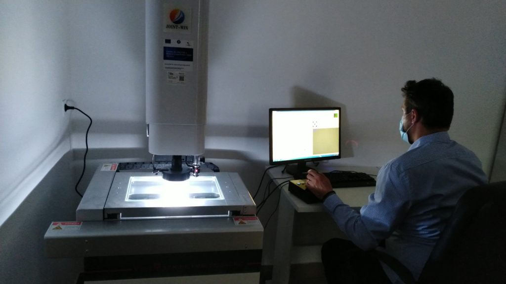
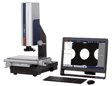
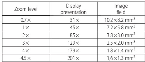
Accurate dimensional measurements are done using MM1-300/6X GARANT Measuring microscope with incremental measuring system, image processing, 1.3 megapixel color camera, and a Multitouch panel based on a PC.
Incident light: 56 white LEDs in 2 concentric rings. 1 ring and 4 segments can each be separately switched and dimmed. Transillumination: LED, telecentric, can be switched and dimmed. Solid granite base with steel cross table, surface hardened mounted on precision needle bearing. Diode laser as positioning guide. Very high repeat accuracy due to automatic edge detection. With 6-stage raster zoom lens, magnification 0.7× to 4.5×.
Moeller-Wedel Optical Elcomat vario D 500T/65 electronic autocollimator may be used to set/determine the perpendicularity to a given surface.
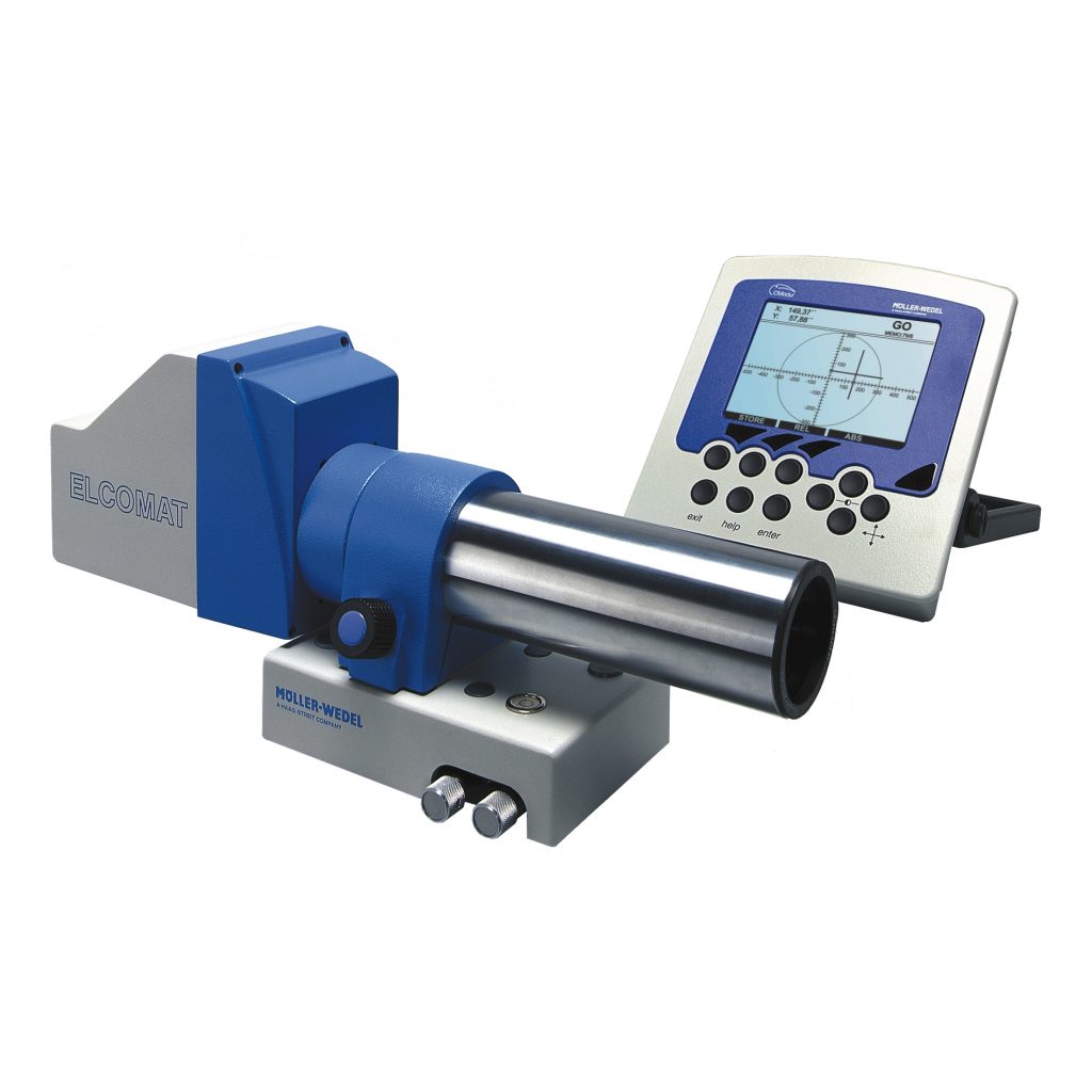
- Measuring range: 0.4 ° on x-axis, 0.3 ° on y-axis
- Recommended resolution: 0.05 arcsec
- Accuracy: ±0.4 arcsec
- Reproducibility: 0.05 arcsec
- Focal length: 500 mm
- Free aperture: 50 mm
SPECTRAL ANALYSIS OF MATERIALS
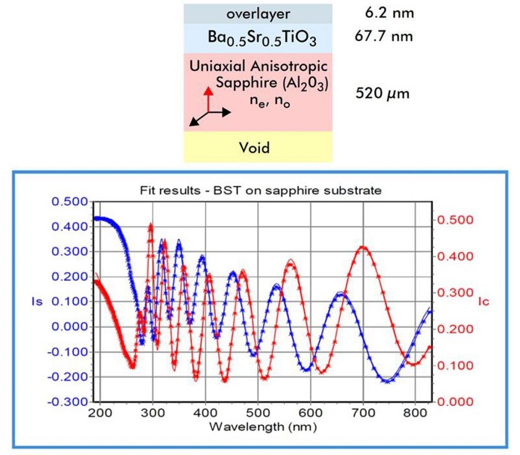
Spectral analysis of materials is mainly useful to characterize thin films, as optical coatings, but may extend also to bulk or liquid materials. The measurements comprise spectral characterization of optical coatings or thin film filters in a wide spectral range (UV-VIS-NIR), using a spectrophotometer, thin film thickness from 1Å to > 45µm, depending on material absorption, optical constants (n,k) for isotropic, anisotropic, and graded films, surface and interface roughness, derived optical properties such as absorption coefficient α and optical bandgap Eg, material properties: compound alloy composition, porosity, crystallinity, morphology, uniformity, Mueller matrix and depolarization, using an ellipsometer.
PerkinElmer LAMBDA 1050 UV/Vis/NIR Spectrophotometer
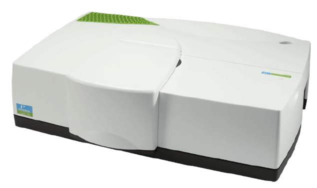
- Detector: high energy R6872 photomultiplier in all UV/VIS range and InGaAs with an efficient Peltier cooling system for NIR range.
- Source: Pre-aligned tungsten-halogen and deuterium. Utilizes a source doubling mirror for improved UV/Vis/NIR energy.
- Spectral range: 175 nm – 3300 nm (N2 purge required below 185 nm).
- Resolution: UV/Vis < 0.05 nm, NIR < 0.20 nm.
- Wavelength accuracy: UV/Vis ± 0.080 nm, NIR ± 0.300 nm.
From thin to thick layers, with or without a transparent substrate, in the fields of semiconductors, flat panel displays, optoelectronics, photovoltaics, and optical and functional coatings, it is the best solution for precise characterization of thin film structures.
- Spectral range: 190-2100 nm.
- Photoelastic modulator.
- Software: data acquisition, modelling and interpreting.
- Surface and interface characterization.
- Determines refractive index and extinction coefficient of thin films, multilayer structures, bulk materials and liquids.
Obtained information
- Thin film thickness from 1Å to > 45 µm, depending on material absorption
- Optical constants (n,k) for isotropic, anisotropic, and graded films
- Surface and interface roughness
- Derived optical properties such as absorption coefficient α and optical bandgap Eg
- Material properties: compound alloy composition, porosity, crystallinity, morphology, uniformity
- Mueller matrix
- Depolarization